Blogging has brought me enough fame that Altium asked me to review their FPGA development system called the NanoBoard 3000. I knew that Altium offered schematic capture, simulation and PCB layout tools.
This was my first look at how I would design at a block level and then see my hardware design in an FPGA without getting stuck in too many low-level details or even using RTL coding.

NanoBoard 3000
I was first contacted by Barry Katcher of McClenahan Bruer Communications, a high-tech PR firm located here in Portland, Oregon.

Barry arranged a phone meeting with Marty Hauff of Altium, and he explained how the Altium Designer software is intended for electronic designers that use building blocks to put together a system with both hardware and software.

Marty Hauff, Altium
Installation
I was able to download and install the Altium Designer software from the web and then discovered that I also needed the Xilinx ISE software. My laptop is running Windows 7 Pro 64 bit and Xilinx didn’t support that yet, so I had to reinstall everything on my older Windows XP Pro computer system instead. Xilinx has multiple gigabytes in the ISE 11.1 download, so it took awhile to get installed.
Tutorials
I really liked the Altium approach of using Videos to show how to work through their tutorials. The first tutorial was building an LED controller with schematic capture.

After I added blocks for the LEDs and wired everything up I just clicked a few buttons to get my first hardware design into the FPGA on the NanoBoard.

Subsequent tutorials built upon this first example and showed how I could start to add virtual instruments.

I could even get fancier using HSV values for my LEDs.

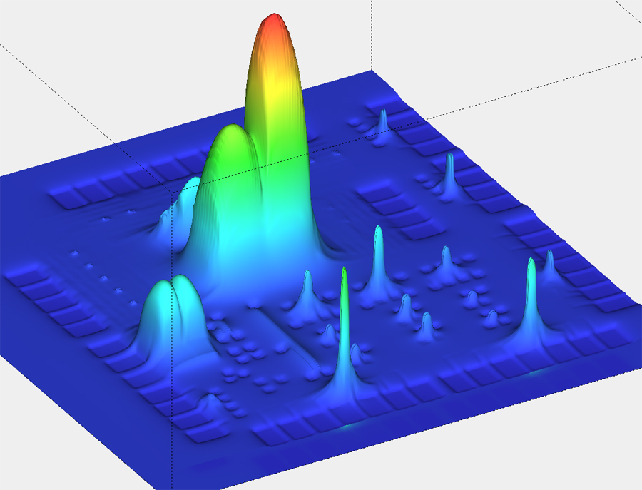
The Sound To Light tutorial even used a microprocessor core.

Obstacles
I did run into a software bug in one tutorial and Marty gave me a work-around by editing a .XML file in the Xilinx synthesis flow.
A few times I had to restart the Altium Designer Software to get it back to normal.
On the Sound To Light tutorial I found out that using a microphone input wasn’t producing enough voltage swing, so I used the output from my PC sound card to drive the NanoBoard line input instead.
Summary
Altium has really made FPGA design for electronic designers simple and enjoyable using the NanoBoard 3000 development system along with their intuitive Altium Designer software. The NanoBoard 3000 is absolutely loaded with features:
- High capacity FPGA (Xilinx, Altera, Lattice)
- Integrated color TFT LCD panel (240×320) with touch screen
- High-quality stereo audio
- USB hub
- SVGA interface
- RS-232, RS-485,
PS/2, 10/100 Fast Ethernet, USB 2.0, S/PDIF, MIDI - Dual SD card readers
- IR receiver
- Programmable clock
- 4-channel 8-bit ADC
- 4-channel 8-bit DAC
- 4x isolated IM Relay channels
- 4x PWM power drivers
- 8-way general purpose DIP-Switch, 8 RGB LEDs, 5 PDA-style push
button switches and a Test/Reset button - User prototyping area
- Dual 18-way (20 pin) I/O expansion headers
- On-board memories
- Four 8Mbit SPI flash memory devices
- SPI Real-Time Clock
- peripheral board
- Board ID memory
- JTAG communications
- PC interconnection through USB 2.0

More info about Altium from John Blyler: http://chipdesignmag.com/display.php?articleId=3991
The NB3K is a tinker’s delight, for sure!
It is amazing how much information Marty can compress into the few minutes of those videos. I find myself riding the pause button to just absorb one point before the next few flush my short term memory. Somebody please invent a video playback speed control.
Ron,
I agree, Marty did a fine job of presenting the concepts and the videos do move briskly.
I think that other EDA companies can learn a thing or too about using videos from what Altium has produced.
My previous experience with FPGA development boards was using a Lattice MachXO Starter Board and it was very bare bones by comparison, plus no videos to watch.
I’ve been using the Altium stuff for many years and their service support is TOP NOTCH EXCELLENT! They always have some training / show & tell going on, lots of upgrades, and their documentation has always been top notch. Their libraries seem a little dated but there is SO much in there…I have only had to make a few very specialized parts. Multilayer board layouts are easy and have more features than I can use.
My three wishes are:
1 for them to fully integrate their physical designs with Inventor (not too likely to happen) but I can dream.
2 a website to upload parts/pieces for integration by their folks into the libs so we can all share
3 a BIG discussion on formats for lib components to make a good library into the best
I have to agree the ISE is HUGE. Start a download NOW if you are thinking of setting it up.
Doc,
Thanks for sharing your experience with Altium.
The best and most successful EDA companies really listen to the wishes of users and then set a course to satisfy a segment of those wishes.
I like your idea of a shared library.
Daniel